We are still on our route from Product Requirements to System Requirements. In this post we would turn a very initial and top-level block diagram into a more detailed architecture, one that may be negotiated with Product further down the development path.
If you have not yet read the first post in this series stop now and go back to read it since everything in this post is derived from the content of that post.
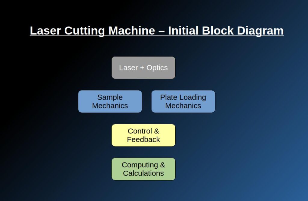
A little recap of where we left in the previous post: the following initial design is our starting point
Technology Research Stage
This is the most fun part in any development process!
Using the top-level architecture as a guideline, we have to breakdown which subsystems we will have to design for such a task. A cutting laser, sure, but the supporting modules around it also present their challenges.
What we have to identify is which technologies are available for our system and what is the limiting factor to be solved in each module.
And the best of all, we can do whatever we want – there are no real limitations at this stage.
Laser Unit + Applied optics
This is where the pure optics and photonics expertise come into play, as follows:
- Laser source module, with the following sub-modules: laser source, power supply, cooling sub-system. Quick research shows that the required power of the laser is somewhere in the range of 10-12kW of an NIR laser, around 1070-1080nm. IPG Photonics YLS-20000 and Raycus Lasers C12000M-HP can definitely do the job. Prices tag 80-100k$US per unit. BTW, those of you with a keen eye will have noticed that the IPG photonics already have in their portfolio a “competing” product that does essentially what we came here to do
 . For the sake of our exercise let’s ignore this product’s existence.
Fortunately, these lasers are fiber-coupled which solves the problem of laser beam delivery to the sample area – we can thus at the outset cross that systematic problem off our list. - Beam shaping, focusing and movement on the sample: having the laser beam reach the sample area is not enough. Because we are dealing with a very big mass of sample (250cm x 150cm x 15mm aluminum plate that weighs around 150kg and the stainless-steel plate goes up to 450kg) it would be mechanically wise to get as much movements done as possible by shifting the beam itself and not the sample. In addition, I assume that different beam shape and foci will change the cut profile so these phenomena have to be taken into consideration when we do initial research testing with the laser unit.
- Stray light handling: in the NIR range, not all the photons are absorbed in the aluminum or stainless steel. That means that some portion of our laser beam energy is reflected off the surface of the plate we just came to cut. For both machine and human safety this reflected light has to be attended to.
Mechanics for the Sample
The mechanics for the sample is what holds the cut part during and after the cutting process.
- Plate holder + XYZ movement: whether we want it or not, the plate must be held inside the active area and move into the cutting area. Whether it would be an XYZ or only one of the axes to be determined (TBD).
- Plate cooling: assuming absorbance of up to 45% in stainless steel (7% in aluminum) and a 12kW power laser there is going to be up to 5.4kW of heat to dissipate from the plate area. Cooling the whole plate area during cutting operation is a necessity.
For example, that if the plate cooling was utilizing water as coolant, it would mean that this is sub-system would also require coolant handling and removal and obviously constant water stream supply. In other words, this little title “Plate cooling” may appear plain and simple but it might turn all of the system design upside-down to support. - Debris removal: we are about to use a high-power laser to separate metal parts – there are sure to be debris and other leftover materials as part of the process, including small sized pieces of metal that would probably go to a recycling bin of some sort. This is the sub-system that deals with evacuating all these leftovers.
- Ready part mechanics: some technical solution must address how to handle the plates once the cut is finished. If we address the cut parts as a puzzle of plates separated only by the cut width the whole plate with the cuts may be extracted on some kind of a conveyor. This sub-module may be optional, depends on later negotiations with Product.
Plate Loading Mechanics
The plate loading mechanics serves the system to insert the unprocessed metal plate into the machine.
- Plate pick & place mechanics: not much to explain about this topic’s functionality .
- Plate rack removal mechanics: if automation is entirely complete the plate rack itself has to be removed once the max of 25 plate stack has finished processing. Maybe nice to have but requires negotiation with Product.
Control and Feedback Sub-Systems
The control and feedback sub-system are usually divided into 2 kinds:
- A parameter or characteristics that are required to keep the system performance in spec and needs to be monitored and\or controlled.
- Special needs defined by Product which can be regulatory aspects or clients’ requirements.
As follows:
- Plate characteristics identification on load: plate size, thickness, shape etc.
- Plate placement feedback & control: the accuracy of the cut is a key technical requirement. The placement of the plate has a lot of impact on this accuracy.
- Beam shape feedback & control: once again, impacts a great deal on accuracy and “cleanliness” of cut.
- Beam location feedback & control: the beam location and the plate location are complementary for the cut precision.
- Beam intensity feedback & control: different metals, different metal thickness and different profiles require different beam intensity. This control
- Cut progress feedback & control: doing constant monitoring and correction (control) of the cut progress allows better systemic control of the cut accuracy to comply with the performance requirements.
- Laser cooling control: acts as a safety measure for the laser.
- Sample cooling control: acts as a safety measure for the sample itself and for the sample area in the system.
Computing & Calculations
There are going to be many computing and calculations of course. We address only the algorithmically complex ones, the ones that will require effort and research.
- Calibration flows: a System Engineer’s wet dream is to have all the calibrations of a machine automated such that once the tool is installed no-one has to deal with the machine’s settings, that is at least until the next periodical maintenance arrives and we have to grease the rails. To realize that dream, as close as possible, the following auto-calibrations would be advisable. Currently a short list would be something like: Laser intensity, Laser focus, Motors’ movements, Coolant flow.
- Laser intensity profile: the laser intensity profile is expected to be a multi-parameter algo. It would definitely require some experimental research and effort.
- Cut trajectory: the cut trajectory optimization will determine the system’s throughput which was already defined as one of the main key requirements for the system. Smart pre-calculation will optimize it.
- Parts handling scheme: off the top of my head, I could not figure out a generic method to handle the ready parts and as a result this bit has to be via algorithmic design.
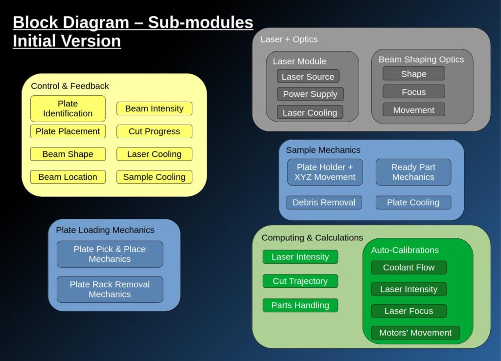
All the details above have expanded our block diagram into a wider and deeper tree which look like this:
Interfaces
Defining the external and internal interfaces of a system is a crucial part of the system complexity understanding both technically and product-wise. It is based, obviously, on the block diagram so similarly it will be a kind of an initial version of it.
External interfaces are the interfaces of the machine with the client’s environment thus these interfaces make an impact that has to be communicated to Product.
Internal interfaces are inner connectivity relations between the different sub-modules which impact the System Requirements and each discipline’s needs.
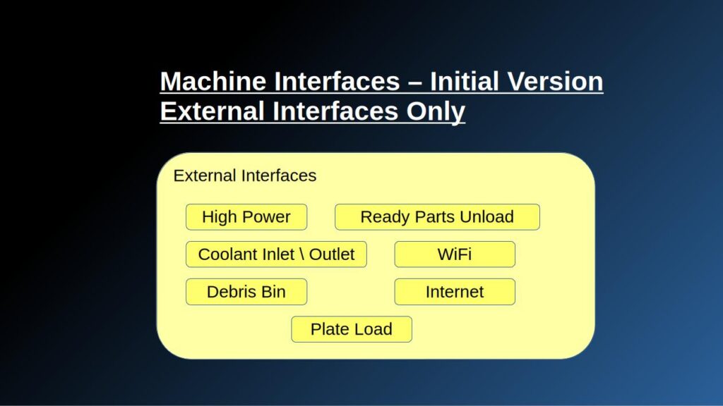
The following external interfaces can be mapped at this stage:
- High power inlet: in the initial hardware research the laser units found required 480V power input. Not standard.
- Coolant inlet \ outlet: whether the coolant is liquid or air flow (or any other gas) we would need and inlet and probably also an outlet of that coolant from the facility.
- Debris bin: goes without saying – one way or another the debris have to be removed from the system facility. Even if it is not done automatically the interface towards the facility is there.
- WiFi: for machine control, interfacing with facility manufacturing computation etc.
- WiFi with stable internet connection: for SW updates, support, licensing etc. (Product are definitely going to question this interface).
- Plate loading platform: the client has to somehow load the plates onto the machine – this interface has to be considered.
- Ready-parts unloading platform: exactly like the plate loading platform, the read-parts need to be removed off the machine in order to continue working on new material.
Since the internal interfaces, because they are so strongly dependent on the system architecture, are expected to change a lot during the development process and in order to keep things simple I will keep the interfaces list only with the external interfaces for now.
Initial System Requirements & Negotiations with Product
If it was not emphasized before, requirement compliance in the system level is something that must be communicated and re-communicated again and again during development process.
As a matter of fact, we may definitely call the child by his name: negotiating. The reason it is negotiation in practice is because there is a cost for every technical feature and the give-and-take game of which features go into the product and which do not. There are usually two sides to these negotiations: System Engineering that represent the technical side and Product Department that represent client and market needs. BTW, when the negotiations fail the CEO has to act as King Solomon ![]() .
.
One output of these negotiations is the Key Performance Requirements (KPRs) which tell us System Engineers what in the to-be-product is major feature without which we cannot ship the product to the client. Remember that these KPRs may also change during the development process.
See below a simulation sketch of the negotiations flow:
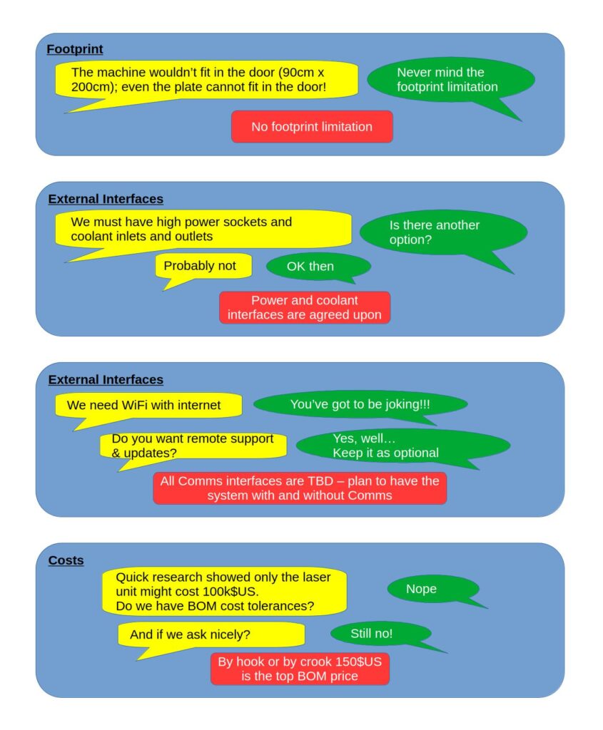
This is obviously a very small part of ping-pong discussions between the technical team and the Marketing and Product teams which was written in a bit of humorous way to the best of my abilities.
There is a catch in such discussions – the quality and accuracy of the answers given by Product & Marketing is as good as the way they phrase the questions and issues. When we phrased it as “we must” and “no other option” it is a compromise that the product will have to suffer in order to have some kind of a product. As such, we have to be absolutely sure when we use the words like “must” – “with great power comes great responsibility” as Uncle Ben rightfully advised Peter Parker. On the other end of the scale if there is a feature that is lost due to market limitations it must be communicated properly for example remote support and auto-updates in our case. It was clearly communicated such that Product and Marketing postponed the final decision for later stages (as TBD) to be able to assess this trade-off properly.
System Design & Go-to Block Diagram
These two phases – technology research → top-level design into refinement of requirements by Product & Marketing can be a very long process (sometimes years).
Let’s assume we have done a few iterations to reach the following design that includes essentially everything that was discussed in a bit more detail and with the realization that Electronics & HW deserve their own block:
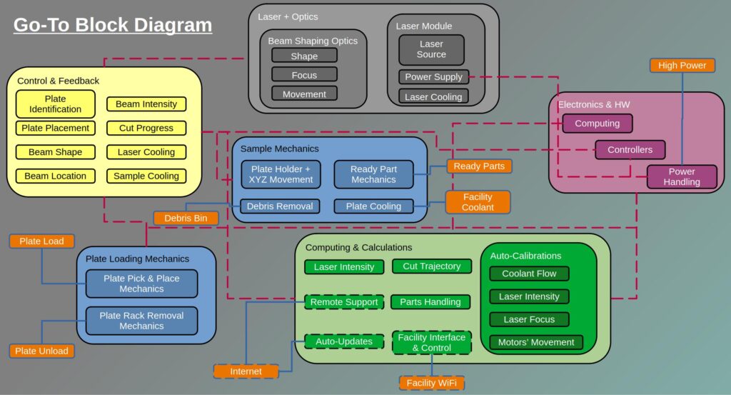
This is an excellent milestone as a stopping point for this post. In this post and in the first post in this series we have established what would be the base design of our metal cutting system, still very top level, even though it does not seem that way. This design will serve as the base for our next post – formulating to System Requirements so that the team will eventually develop the system we want as accurate and as smooth as possible.