
Recently I realized that a very large portion of my day-to-day, in complex systems in general and specifically in optical systems, is spent on designing the alignment processes and calibration procedures for the system. As such, the purpose of this post is to give a little taste of the importance of the alignment procedure for the system’s right-to-exist. You may look at this post as some kind of continuation of the Tolerance Analysis post.
It all started when I was a junior physicist: I came across a beautiful design for an optical device that was required for the product I was working on. Not a must, but a potential improvement over the competitors’ performance benchmark. The company purchased all the required optics (all custom made) and manufactured the mechanics. I went into the laboratory and indeed at first glance that design was beautiful. I kept playing with it only to discover that I did not have any method to get the device into its stated performance window, in fact far from it – less than 70% of the specifications. The device had multiple degrees of freedom to correct the optical path however, there was no alignment procedure nor any accurate feedback mechanism for me to use in order to have that device working properly. Unfortunately, the designer could not assist and all of this device’s components were scrapped.
The moral of this story is that even the most glamorous designs are useless if there isn’t a method to align and calibrate them into the system.
Please note that for the purpose of this post-series alignment will fix manufacturing and initial positioning errors. If during operation of the system there needs to be some drift corrections etc. these are dynamic DOFs and are not part of the content of this post-series.
Tolerance Analysis Output
We have already discussed in a previous post what are the outputs of a formal tolerance analysis that is conducted properly. One of the outputs of the tolerance analysis is an alignment Degree of Freedom (DOF – not to be confused with the optical Depth of Field DOF).
Identification of the need for alignment in an optical system is an important step towards performance however; it is only a small fraction of it. I have seen my share of system architectures that were ruled-out simply because one DOF that was impossible to accurately align.
There is one point that must be emphasized regarding tolerances: be realistic – for better or for worse! Do not simulate a tolerance of 50nm when at best you may get 1um and do not simulate 1mm when the CNC may get you to 60um “just in case”.
One more issue about tolerances – there are sometimes differences between the sales brochure’s accuracy capability of the vendor and the case-specific accuracy capability. Check with the vendor and if not sure ask for a sample of verification of the tolerance. A good practice is to compare the vendor’s numbers to the industry standard within the same price range. If the tolerance range is much better (or much worse) than the standard, challenge it.
In any case, the output of the tolerance analysis is our starting point for the alignment process.
Alignment Procedure – Where to Begin
With a 2-element optical system I imagine that “where to begin” is not a real issue but when dealing with a 20-element optical system with motors and multiple moving elements the starting point of the alignment could be a challenge in itself.
Unfortunately, there is no secret procedure to identify the starting point or the pivot elements for an alignment other than experience. My rule of a thumb is to identify 2-3 elements for which each DOF adjustments would require adjustment up stream i.e. cause re-alignment of previously aligned elements and set all or one of these elements as pivots. Setting the pivots correctly usually dictates the optional starting points of the alignment.
Alignment Procedure – Flow Outcome
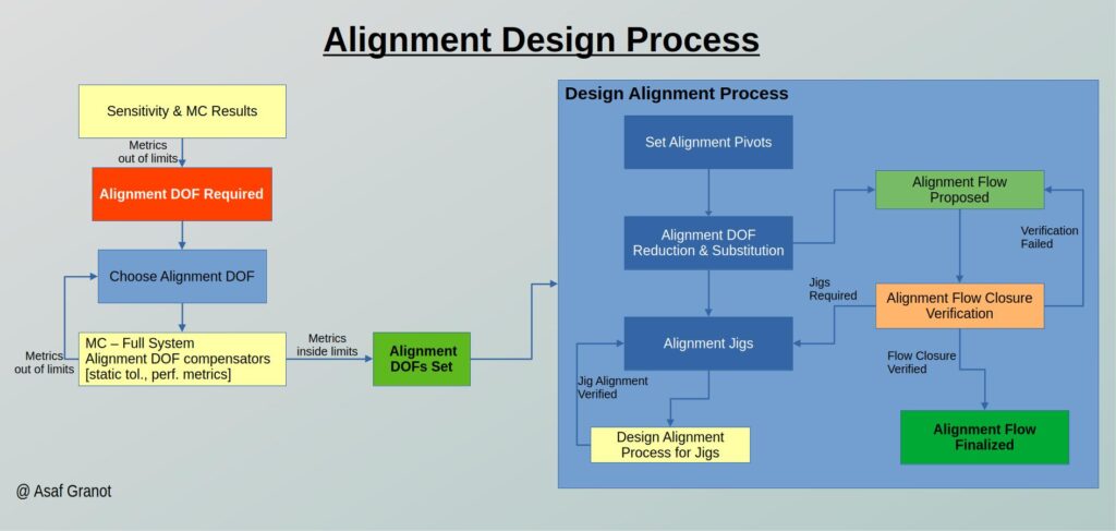
Every alignment process must finish in one of two possible outcomes: aligned system or scrap material. This derives that each alignment step of the process must have a feedback and end with a range of acceptable values for this feedback. Each verification step must include what the next step is in the case that the verification passes but more importantly what is the procedure if the verification fails.
In complex enough systems, when Monte-Carlo’ing an optical system for the different alignment steps with solvers or optimizers each and every solver has to converge in order to assure a full-proof alignment procedure. If the solver does not converge in 100% of the Monte-Carlo iterations it means that someone in the assembly line will have to solve this gap for us! Remember that if in a correctly-simulated the convergence is less than 100% it will not be suddenly better in the assembly line.
Obviously, there are manufacturing costs considerations that must be made. Sometimes not converging in 100% will be a calculated risk – it is OK as long as the alignment procedure covers what has to be done upon failure (element replacement for “cherry picking” or scrap material are the most common strategies).
An optical design without an accompanying optical alignment procedure is only half a design!
An important note: simulating optical alignment procedure with current optics design SW like Quadoa, OpticStudio or Matlab is not a trivial task. Each step has to be simulated with the correct solver that accurately resembles the feedback mechanism for that particular step and also accurately simulates the locations of already existing elements that are the consequence of previous steps. Regardless of what the software being used for this simulation task is, it requires profound knowledge of the different optics elements, the environment in which the system operates, the materials involved and the exact limitations of the feedback systems and their mode of operation. Failing to simulate correctly the different steps of the alignment might bring us to the undesired situation of reassessment of the whole alignment procedure while doing the first integration of the system even without the regular unknown technical risks that hide while designing a system.
Direct vs. Indirect Feedback in Alignment Procedure
Direct feedback alignment means that our feedback measures the exact unit we need to continue. And indirect feedback or proxy alignment means that the units we measure are not directly what we need and there’s either a calculation or an assumption that fills the gap between the real unit and the one we measure. For example, when we want to test the laser power loss of a certain optical element a direct measurement would be to insert a power meter before and after the element while an indirect measurement could be measurement of the reflection of the light from the element and assessing its absorbance according to the temperature rise and subtract it from the input power.
This is obviously an extreme example to emphasize the point.
Before starting this post, I contemplated whether to add this section. It is obvious that direct feedback is always preferable when practical. In the cases where it is not practical (too expensive, cannot fit the system mechanically, cannot be measured directly at all etc.) the crucial issue will be the translation between the chosen feedback value and the real value we are searching for.
For example, if we would like to calibrate the angle of an element facet against a laser line we could use an autocollimator to align the laser collimator front facet as a starting point and then use that very same autocollimator to align the desired element angle. One may ask why would that be considered indirect. Regardless of the autocollimator’s accuracy and repeatability, the answer lies in the difference between the feedback which assures that these too facets are aligned to each-other however the laser line is not necessarily perpendicular to the laser’s collimator front facet. Furthermore, the laser beam entry into the optical element under alignment doesn’t necessarily experience perpendicularity or parallelism in a sufficient enough manner to be considered as granted only because these two surfaces turn out parallel when using the autocollimator.
In such indirect cases we must make sure that after all the intermediate calculations what we eventually aligned is indeed what we needed to be aligned.
Relative Feedbacks
Relative feedback means we take our measurement and get a number that is relative to a certain pivot, for example using an area sensor to measure a laser spot position will be relative to the location of the sensor in 3D space. In addition, it is very common to calculate movement angles and straightness with 2 or more measurements on a single sensing device and according to the relations between the measurement conclude the angle of movement against a certain mechanical pivot.
One may argue that all feedbacks are relative since we zero each sensor to a certain feedback level and sensitivity which is by itself relative to some pivot. When I refer to the term relative feedback I refer to the alignment procedure relative feedback.
This is only to warn that a relative feedback holds in itself a great risk of misalignment or shifted calibration because the pivot to which we thought we get the measurement is not the actual pivot of the relative measurement.
Differentiation of DOFs
Golden rule of an alignment step: a step, a feedback = 1 DOF. It means that if I have a feedback over a laser spot position in the horizontal direction and I have 2 DOFs that were not set yet that could change that spot position horizontally this alignment step is bound to fail. There is an emphasis on “were not set yet” because if the procedure is structured such that we set during alignment one upstream DOF into tolerance and then later in the procedure set a second DOF downstream that both eventually have the same feedback – that is OK and even required.
This rule must not be broken in an alignment process.
There are cases where the feedback possibilities are limited and an iterative alignment has to be performed where we redo the same steps each time going through the same DOFs until we converge into tolerance. Try to collapse to iterative alignment procedures as little as possible – these are dangerous processes that cause a lot of headaches to the integrators and technicians in the field.
Jigs
In optical alignment jigs are a part of life – whether a sensor with its applied optics, an illumination assembly for an intermediate plane imaging, lens assembly calibration system and so on.
There are a few important notes when introducing jigs into our alignment and calibration processes:
- “Quis custodiet ipsos custodes?” or in human language “who is guarding the guards?”: The jigs are being used for alignment but we have to ensure that the jigs themselves are aligned and calibrated periodically and if in the course of the jigs alignment process we use another external tool we must ensure that this tool is calibrated at all times.
- Procedure: Jigs alignment and calibration procedure must be a part of the general system alignment procedure. If off-the-shelf tooling is being used a periodical calibration must be applied.
- System with and without the jig may differ: Jigs are not part of the system and they are being removed after they’ve served their purpose. Removal of the jig can leave the system in a different state than intended.
- Jigs act as subsystems: we have to treat the different alignment and calibration jigs as subsystems in our design with all the weight this statement carries. In the simulation phase they have to be simulated with tolerances and all applied variations and when transferring to production each jig has to have a technical owner in Engineering to maintain its performance.
Tip of the day: always identify what the pivots of your jigs are – mechanically and optically – and accordingly assess if the jigs are adequate for your optics.
To sum up, this post uncovered in the theory level the important bits of alignment process in an optical system, though all the practices mentioned above can be applied to each measurement or sensing system.
In the next post we will explore through a practical simulation example how all this comes into play.