Optical aberrations… how many times have you got a comment like “yep, we have a field curvature aberration so we need to fix it programmatically” and scratched your head trying to remember what for crying out loud comma aberration was, and why would you care if there was one in your optical system.
So, for those of you who do not look at ray tracing charts for their living (and maybe also for those who do) here is a complete guide for optical aberrations in an intuitive way that may help you remember them the next time someone mentions them to you.
In both vision and non-vision optical systems we are subjected to optical aberrations. They are a part of life; we cannot avoid them. The only thing left for us to decide is whether these aberrations are acceptable inside our error budget or not.
The definition of optical aberration
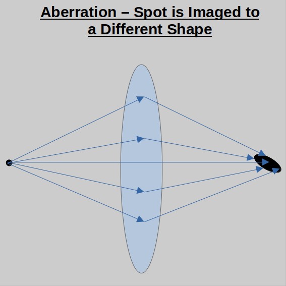
Let’s keep this definition simple without going into any formulae: if we take a bundle of points on our object in an imaging system, an optical aberration is the deviation of the rays from that bundle of points in the final image. In other words when we image a point, we expect it to be a point with the same distance and size ratio to other points in the image. Anything other than that is aberrated. I will refer to vision system aberration in the post as it is more intuitive to explain.
Note: in all the optical sketches in this post the object is on the left and the image is on the right.
A quick word about diffraction limited system and Rayleigh criterion
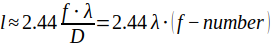
According to laws of physics, when light travels through any kind of aperture it diffracts. Always! This diffraction creates a pattern called Airy Disk, a phenomenon which I will not cover in this post. In practice what we do have to remember is that this diffraction phenomenon widens our beam to a certain size. To what size? Lord Rayleigh gave us an excellent criterion for optical systems where the small angle approximation applies, as follows:
Where
l is the smallest spot diameter in the imaging plane that could be resolved, f is the lens focus length, λ is the wavelength of our light, D is the entrance pupil diameter and f / D = f-number (f/#) of the lens
Bottom line, every optical system is aberrated at least by diffraction – that is the best we could get physically. Such a system will be defined as diffraction limited.
So, we have our target set! We want a diffraction limited optical system! Now back to aberrations.
Focus
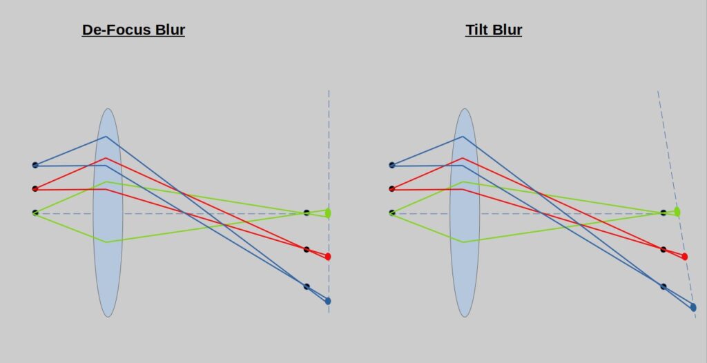
All of you who raised an eyebrow because of the title, you can now stop frowning. If we position our object away from the best focus plane, we get a blurred image. Isn’t that aberration? In my book it is. Eventually we have to solve it to get the image quality we aim for. In focus we could include any kind of disposition of the object towards the optical system. See sketch below where the sketch depicts defocus and tilt in the image plane.
Chromatic Aberrations
When we have a multi-wavelength optical system, chromatic aberration means that each wavelength reaches a different point in the resulting image. A very simple way to look at it is in visible light Red-Green-Blue (RGB) image – the red light is imaged to a different location in the image than the green or the blue. Chromatic aberrations are divided into two kinds: lateral chromatic aberration where each wavelength center of mass (COM) reaches a different location in the XY plane, and axial chromatic aberration where the different wavelengths COM reaches the same location in XY, however their best focus is shifted in the optical (Z) axis. See sketch below.
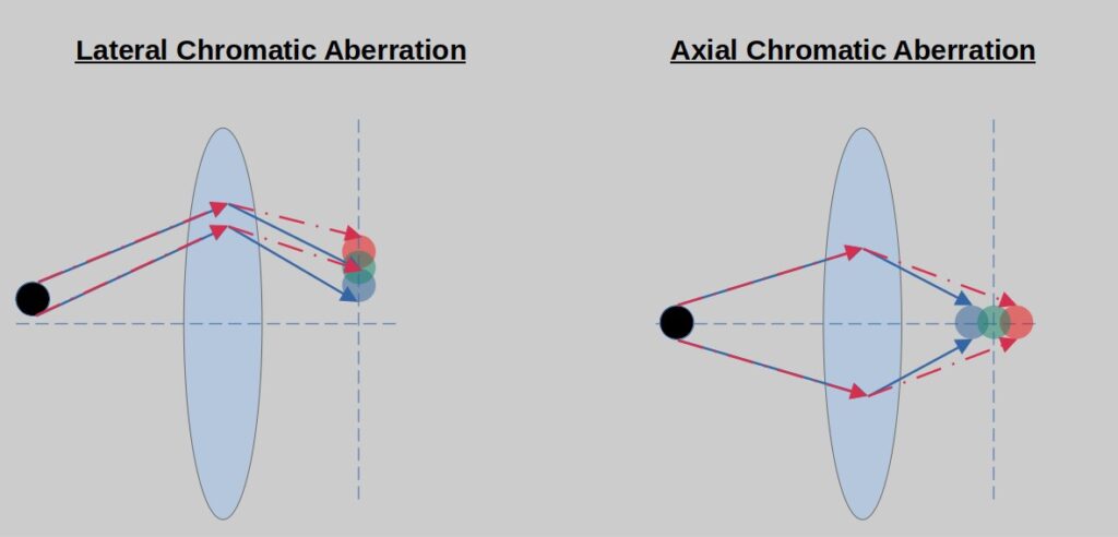
Easy way to remember – any rainbow created by a prism where each colour reaches a different location (well, it’s not really an aberration but it always helps me to immediately remember what colour aberration is all about). BTW, I would have given a famous UK music band’s album cover as an example, but due to political reasons it was kept out of this post.
Spherical Aberration
Spherical aberration is the situation where rays that pass different zones in the optical system get focused in different planes. The COM of all the spots is concentric in the XY plane. See sketch below.
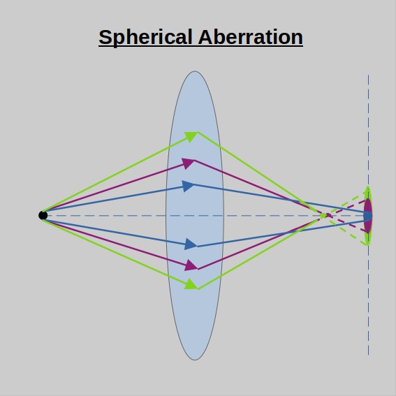
Easy way to remember – spherical aberration is the one you mark a point and draw the circles around it. My way to remember it is darts target.
Coma Aberration
Coma aberration is very similar to spherical aberration, only with axis change. In Coma the ray shift between different zones is in the XY plane, where we may even get different spot sizes originated of different optical paths. See sketch below.
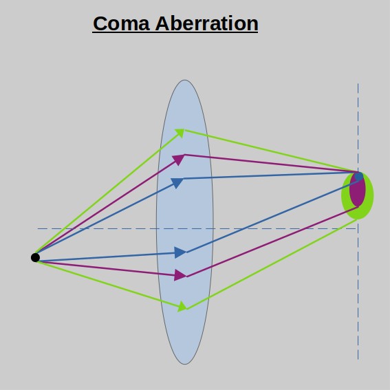
A way to remember it: when someone falls into a coma he falls to his side. A bit lame, I must admit, but it works.
Field Curvature
Field curvature, also may be referred to as Petzval field curvature, is an aberration that we get simply by the fact that our sensors are most likely flat, but the optical system’s wavefront is spherical. This aberration would not really blur the image if we were to choose the “right” sensor. Take a look at the sketch below.
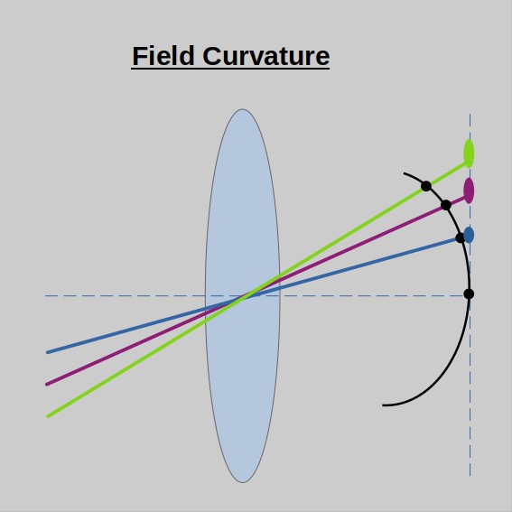
A good reminder for what this aberration is in its name “curvature” which should immediately trigger a curve drawing. Also, Petzval is a name that is difficult to forget.
Distortion
Distortion aberration is a phenomenon where different parts of the image experience different magnification. It does not whatsoever create a blur in the image (the MTF stays unchanged) but the image itself ends up lacking its inner proportion. This is a special case of aberration that I would like to dwell on since we mentioned before that optics and algo are one. In this particular case, if planned correctly with the right camera pixel resolution, we could easily choose to fix this aberration in Algo without the loss of optical resolution instead of having it fixed in optical design. It will come down to the different system trade-offs in such a case.
There are two common symmetric distortions: pincushion and barrel. See sketches below.
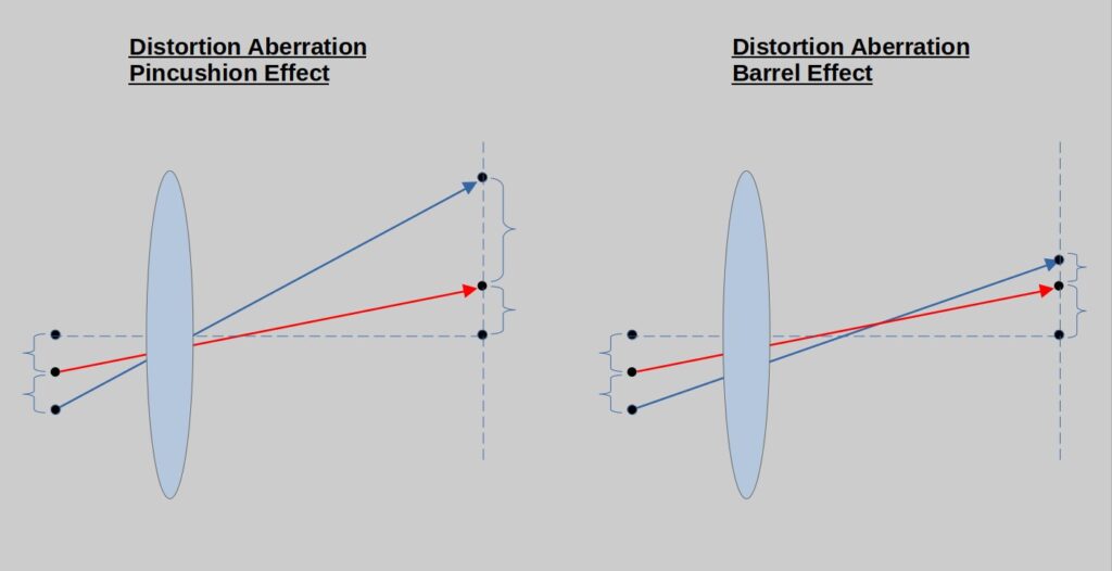
The way to remember this aberration is by remembering that barrel is a distortion aberration. Who does not remember what a barrel is?
Astigmatism
Astigmatism is an aberration caused when the sagittal and tangential rays focus in different positions in space. We have covered what the sagittal and tangential planes in a previous post. BTW, It is easy to deduct that by definition on-axis aberrations cannot be Astigmatism.
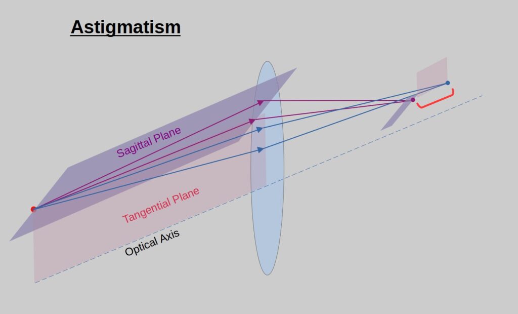
Regarding a way to remember it, sorry, I don’t have any good advice. That’s the one we just have to remember.
That’s it. These are the main types of aberrations we could expect to see in an optical system: two mainly chromatic aberrations i.e., lateral & axial chromatic aberrations and six mainly monochromatic aberrations i.e., focus, spherical, coma, field curvature, distortion and astigmatism aberrations.
In this post in a very simplistic way, between better or worse methods to remember the different types of aberrations, I have covered only the main aspects of optical aberrations in an optical system. There is however much more to it; wavefront and ray representations, spot diagrams, ray diagrams, firth order aberration, calculation of Seidel sums and more and more. This is definitely only the tip of the iceberg in a very complex subject in optical engineering and for which, I am sure that, in the future I will write a continuing post dealing with the deeper aspects of optical aberrations.