Event-Based cameras may serve many purposes. Until now, in the previous posts in the series, we have discussed the top-level characteristics of event-based cameras and different ways to focus the scene but we haven’t really shown a real-life example of an application that could benefit from these characteristics.
As mentioned in before, the event-based cameras have an inherent advantage in shooting very fast changing scenes where as in standard cameras it would require the order of 100K to 1M frames-per-second (FPS).
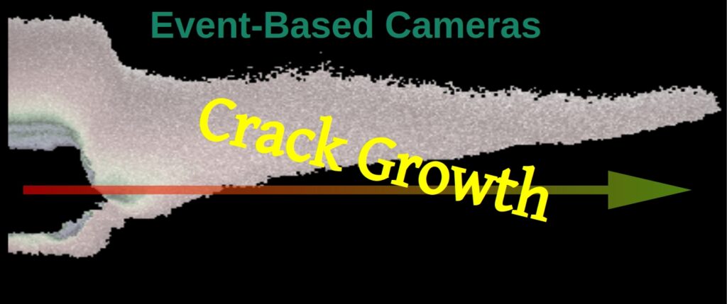
Crack Growth
One such case is the task of mapping the evolution of a crack in a material breakage scenario. Have you ever paused to wonder how a crack propagates through a material from the moment it initiates till the material completely separates into two pieces?
Quite frankly, I hadn’t given it much more than a second’s thought and that was until my friend Prof. Shmuel Osovski Head of the Computational and Experimental µmechanics of Materials Lab at the Technion, Israel Institute of Technology drew my attention to the subject.
The mechanical physics behind it seems to be very simple and straight-forward. Once a defect (e.g. a crack) exists in a material and that material experiences a sufficiently large force, the crack will start extending until we are left with two pieces of material instead of one. Well apparently, that’s only the tip of the ice-burg and that’s putting it mildly. Not surprisingly the crack growth process is still not fully understood and is governed by multiple factors, so the term “simple” cannot be applied here. Furthermore, “slowly” is a matter of perspective and in our case the whole breakage effect end-to-end was in the order of tens of milliseconds – not slow by any practical definition.
As it happens, we may even force crack propagation to follow a predefined path, which will come in handy in certain applications, such as design of packaging for ensuring reliability of electronic components or in satellites manufacturing where a “Design for Demise” approach is used to minimize hazards from space debris is under for example, the safety issue in the case of a complete fall-down in which we want to make sure that a certain structure falls only in a certain direction and not another.
Practical Mapping: Crack Propagation
The experimental setup was as follows:
The camera used was the IDS Imaging EventBasedSensor Eval-Kit ES with the Sony IMX636 with the Prophesee SDK equipped with a X5 Mitutoyo objective and a simple wide angle RGB LED back light. The camera was provided by courtesy of OpteamX.
The sample was placed between the LED illumination and the collection optics. The sample was pinned on one side to a stationary block while attached on the other side to a high force loading device.
The focusing method we used was imaging-optics (camera and lens attached to it) lateral movement as well as focus → defocus shifting, all that in the presence of LED front illumination that was introduced to the setup only for focusing purposes.
Two samples were measured using this setup. The first sample was a 4340 steel that had a simple straight notch in it, on the right side of the Field Of View (FOV). I will not go into the choice of event representation here in this post – we covered the available options in a previous post. Color-by-time representation where every pixel may be lit only once in the movie would be a very good representation method to see the crack propagation in time, as follows:
The color scale is in seconds.
The cold colors of purple and blue are the first 5ms of the recording, through the green and yellow which are the next 5ms until the red and white that represent the final 7ms. The total duration of this movie is 17ms. The accumulation time of each frame is 100us.
“we needed a 10K FPS camera to image that”
This is a very good example of the capabilities of event-based sensing technology. To achieve a similar result with a standard camera we would have needed a 10,000 FPS camera and even that is only because the 100us accumulation time was chosen for practicality reasons for presentation purposes. Researchers may require even finer time-resolution and we could have gone down even to 5us time-steps.
A quick description of what we see in this movie: on the right side of the movie, we see the original crack as the black width between the blue lines. The crack widens until the separation point of the upper and lower parts of the material, sometime around the 12th or the 13th millisecond of the recording. In this particular movie it is a bit difficult to see the exact propagation of the crack in the material before the two pieces, the upper and the lower, completely separate.
To show how sensitive this scene is, let’s look at the exact same movie but we will stop it after 15ms instead the former 17ms:
The coloring is essentially the same only the red ends on the 15ms mark.
We may see in this movie the exact formation of the triangle shape of the crack just before the real separation of the material starts, and if we zoom-in in a still photo we get the following image:
Practical Mapping: Controlling the Crack Path
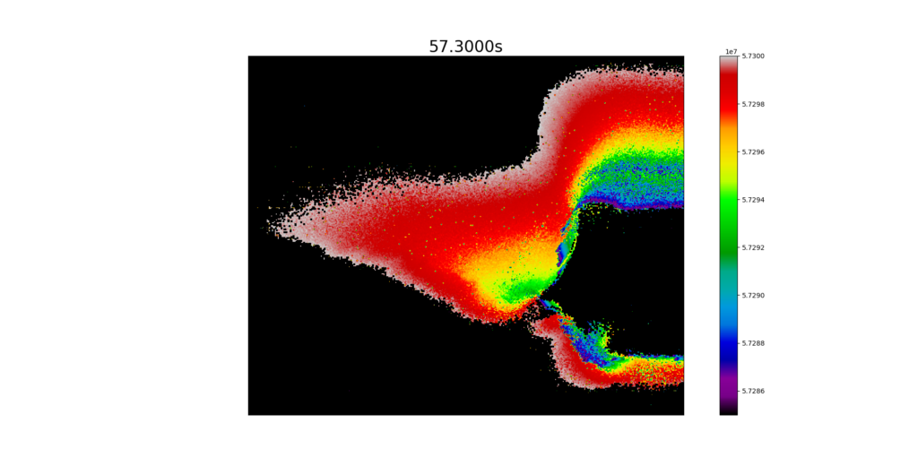
The second sample we used is much more interesting. The initial notch was approximately the same width and depth but right next to it there were 18 holes shaped in two and a half sinusoidal cycles. You may read more about this method of engineering of the crack path here. The experiment itself was the same – we used the loading device to separate the material into two. In this sample the material was Aluminum. Let’s take a look at a 20ms long movie of this sequence.
How cool is that! The crack’s propagation forced its way through the shape of the sinusoidal holes, then continued its movement straight into a triangle shape, before tearing apart the material completely into 2 pieces, as if by drilling those holes we paved the way for the crack to evolve and propagate. You cannot look at this without recalling the joke about the Russian toilet paper ![]() .
.
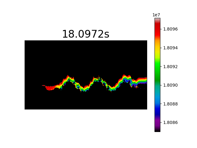
Once again we will use the same trick and shorten the movie length to 12.2ms as follows:
Now we can clearly see that the fracture first propagates to create a continuous line from right to left in the path of the sinusoidal pattern. When the continuous fracture has reached the furthest hole on the left the sinus pattern starts to widen and propagate the crack even further left into the same triangle shape at the edge, similar to the one we saw with the first sample without the holes.
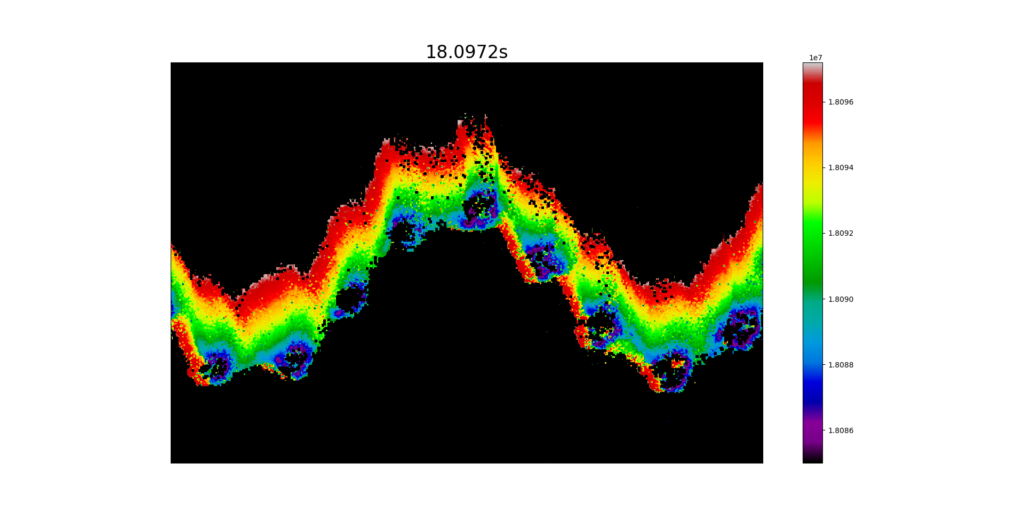
Some of the phenomena are easier to observe using the still images – see below
and zoomed in on the sinusoidal shaped crack
optical resolution suddenly doesn’t have the same meaning
A quick word about optical resolution: the optical resolution we achieved by using this tech could be considered better than the optical resolution we would have gotten using a standard camera. To allow movement detection in a standard frame-based movie we would have to compare between 2 consecutive images in our image processing flow – if the change is pixel size but smaller than the optical resolution of the optics and it is within the basic noise levels of the camera, we would be unable to observe that change in the movie.
In an event-based camera the sensitivity of an event is in the pixel level so the frame level noises do not apply – only pixel level activity. It has a clear advantage in detecting subtle changes in the scene as mentioned repeatedly however, resolution enhancement methods like sub-pixel resolution or PSF based reconstruction and even convolution networks (AI) do not work at least not as is, since they are based on the inter-relations between the pixels and areas of the image to work best.
This does not mean that in the future new methods to achieve any of these will not present themselves– it only means we have some interesting image processing methodologies and algorithms to come. I will probably dedicate a post for these methods in the future.
Note that the neuromorphic camera would not have been a suitable choice for this task if in reality the experiment was sensitive to colors and not just the existence of light. For example, if the scene’s go-no-go data was in red-shift vs. blue-shift the choice of event-based camera would have been a very poor one.
In this post we have demonstrated one of many applications of event-based cameras, an application where the order of the flow of events is crucial and the whole sequence is very fast. But most importantly, we achieved an equivalent of 10,000 FPS and even more with a small USB-3 industrial-shaped camera, without the need for a fancy illumination, without a multi-K Euro camera and even without a synchronization signal. A simple “point-and-shoot” for a job otherwise very complicated.
Once again, I would like to thank Prof. Shmuel Osovski for the kind use of his laboratory gear and thank OpteamX for lending us the camera for these experiments.