The task of turning product requirements into System Requirements is the art of a system engineer. What makes this task so complex is understanding the two sides of the end product, the client side and the technical side. We all know that when something is complex those who manage to keep up with its complexity and stay alive are considered artists just like pianists who manage to play a virtuoso piece. To accomplish this is a function of knowledge, practice, experience, more knowledge and more practice and yes perhaps, sometimes, also a talent for the job (A System Engineer is raised or born?).
Laser Cutting Machine
In order to demonstrate the art of it we’ll take a real-life example. To prevent my own professional bias, I will take as a specific example a project in which I never participated in – Laser Cutting! Which reflects my never-ending desire to participate in a James Bond like scene with a cool laser that cuts everything ![]() .
.
So, we will try to walk through the initial System Engineering process until we reach system architecture and initial System Requirements.
This part’s requirements and needs will be investigated deliberately without the direct assistance on any AI prompt (Claude, ChatGPT). I have permitted myself the assistance of AI only for search of a product online and only in order to save time writing this post.
An important disclaimer – there are many (I mean MANY) ways to tackle complex system design and in the example chosen there are many possible solutions (take for example Trumpf machines vs. Bystronic machines, both are commercially available products in the field of laser cutting and you will see that they are not the same solution. Even the laser unit itself is not based on the same technology). What I lay out in this post series is a series of actions to be taken to reach the goal onto a specific solution. I know that there are other ways just as effective and may well be even more effective. Consider it as a thorough example that follows a certain playbook but there are other playbooks out there.
In addition, there are many aspects to a system as complex as the one chosen for this example and it is practically impossible to cover everything. I have tried to cover the main top-level issues and give examples of a few into-the-details complete run-down to show in this example a proper method to reach System Requirements that have their roots in solid ground. As a reminder, everyone makes mistakes as clearly stated in this post and I am no exception especially when all this exercise is in theory. Therefore, please excuse any mistakes I might have made.
So, without further ado, in this first of 4-posts series we will review the system and how to address its most immediate needs.
Step #1 – Understanding What The Product Is
We need to build a Laser-Cutting Machine for the metal processing industry. The product requirements to begin with are as follows:
- Metal types: Aluminum, Stainless steel
- Maximum metal piece dimensions (W,L,T): 250cm, 150cm, 15mm
- Smallest cutting feature: 35um
- Target BOM price: 150,000 $US
I did not take it arbitrarily to the extreme just for the sake of this example. Sometimes that’s the length and the extent of product requirements we get in the beginning of a project for kick-off.
Obviously, we can and are even expected to ask follow-up questions. This does not necessarily mean that we cannot define something that will comply with all the product requirements however, the more information we get the less chance we will have late rejects from Product that will cost valuable time and money.
The first set of follow-up questions that came into my mind are as follows. I have added in parenthesis the answers from the Product Manager:
- Does the calibration have to be automatic? (“Yes, of course!”)
- How many cuts per hour in length [m]? (“The clients want 25 250mm-length plates cut with not-straight features per hour. You do the math” – calculated as 125m per hour for the straight feature scenario)
- Is the material loading automatic? (“Yes, from a platform with piles of 25 metal plates of certain dimensions”)
- Allowed average downtime per week for maintenance? (“You have an hour a week, and even then, be ready for client complaints”)
- What is the maximum size of the machine? Footprint? Height? (“It has to fit in the door”)
These questions arose so as to answer some very important missing information in the original short set of requirements: required speed of the machine, size and up-time on top of the already existing resolution, materials, target dimensions and of course target prices. As mentioned before, we may have started without it but, if we take for example the cutting speed the difference between 20m/hour and the required 125m/hour could be a very harsh chasm to overcome after all the system is already up and running.
Note that there is an inherent contradiction in the answer to question #5 – how can the machine fit in the door if the plate dimensions are 250cm x 150cm? We will deal with that later, there’s no point in addressing this issue now since we know nothing about our design.
Also note that in order to simplify case-study we do not take development timeline or time to market as numeric factors in our considerations.
Step #2 – Technical Translation of The Product
Many junior System Engineers used to ask me at the time “where do we begin?”. Even in smaller scale projects there is a list of Product requirements out of which we have to figure out a complete design.
Starting with translation of the requirement into something more “technical” and mainly numeric is a very good first step. Getting this translation done correctly is sometimes the difference between an impossible project and a doable one. Imagine your translation arrived to technical requirement of a velocity larger than the speed-of-light – you’d probably advise the Product department to seek a different market ![]() .
.
So, in our case the translation of the product requirements will turn into the following list:
- Laser unit with minimum power suitable to cut through 15mm of aluminum and stainless steel in speed of 35mm/s.
- Laser Optical resolution < 35um – with spare margin to be decided upon later, since in most times 35um resolution does not guarantee 35um accuracy.
- Loading mechanism and platform for 250cm x 150cm x 15mm metal plates.
- Auto-calibration support.
- Up-time 95.5% (0.5% for calibration and maintenance).
- Footprint: up to 95cm in width, 195cm in height, length can be negotiated.
These are more or less “technical” translation of the Product Requirements. The first item about the laser is a bit vague at this stage due to lack of information. The remainder of the list is more or less straight forward.
System Requirements doc is an interesting type of technical document. On the one hand the requirements are, well, requirements – a list of technical demands from the system, that is to say they are not the implementation but the expectations of what that system should do technically. On the other hand, the system requirement document is a “live” document that is being updated all the time, especially in the initial phases of the development process where the architecture is still being built and continuously updated.
In our example we will be addressing the list above as the level-1 System Requirements, where the level-2 System Requirements will already take into account that we have an architecture in mind.
Step #3 – Initial Architecture and Block Diagram
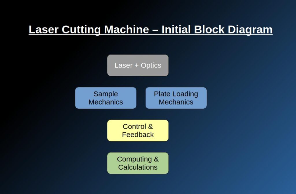
Let’s dive into the list of the sub-modules required to make such a system work:
- Laser unit + applied optics: the laser source is a crucial module in our system and we have to consider the delivery method of the laser beam onto the sample.
- Mechanics for the sample: we have to support moving around the sample inside the active area of the cutting machine, as well as the support mechanics for the ready parts.
- Plate loading mechanics: since it was part of our design goals, the plate loading mechanics is also a crucial module.
- Control and feedback sub-systems: the performance of the whole system will be determined by how we control it and whether the feedback mechanisms we choose will provide the correct data-flow for the system to operate to-spec.
- Computing and calculations: there must be a central brain for such a system. Probably each module will enjoy some independent computing and control which will do the simpler tasks but these all mini-computing modules must be wired and cooperate with a single higher level computing module.
This is the very top-level design of a to-be complicated machine with lots of modules and sub-modules. We will set this as our starting point.
BTW, there is one step that I skipped – the whole understanding of the top-level blocks and their functionalities in a project that starts from scratch is a process that is done with all the top minds of the engineering team. In our case I took the liberty to fill in for all the missing engineers and used my experience in machine design for the different blocks’ functionality.
In real life this process of understanding the initial top-level blocks is a process that may take a few weeks where ideally all the technical staff sit together and throw ideas as to how to comply with the requirements. Usually there are also arguments whether the requirements are really needed or not – but that’s for another post.
There are the cases where the Chief Engineer or Senior System Engineer just work out everything on their own and pass-down the design to the rest of the team. This is however, in my opinion, a faulty method that should be avoided. Even the fresh-out-of-school junior engineers may have something useful to say about implementation and realization of the requirements. Every discipline should be involved in the process at this early stage.
And yes, there is AI. I will address the AI issue later on in this post-series.
This is a good place to stop; we have reached a development mini-milestone. In the next post we will dig deeper into the details of this architecture and see how the architecture tree grows wider and sets up the System Requirements.