More and more often we require methods of visualization for our systems be it from experimental systems to check the simplest thing like reading an LCD digit for QA purposes, through security cameras and autonomous robotic systems and up to a scanning products that are in their technical core optical systems that give the clients their required results. The difference between a perfectly working vision module and a nearly working vision module could be a fine detail that was overlooked in the requirements. As in everything in development we would like to avoid backwards iterations of development or implementation.
Just to emphasize that the definition of imaging systems or vision systems is clear, I refer to every optical system that at the end of which we have some kind of a sensor (camera, human eye) from which certain features have to be extracted. The sensor is also a part of the optical system. For example, a laser system for welding 2 pieces of metal together is not an imaging system, however the camera closed-loop feedback system that looks at that laser welding process and controls it, is an imaging system.
Very much like my Laser System Requirements post , I will try to give, from the optics point of view, a few tips as to what’s important when defining a vision system and the parameters that we must draw our attention to when we formulate a set of imaging system requirements.
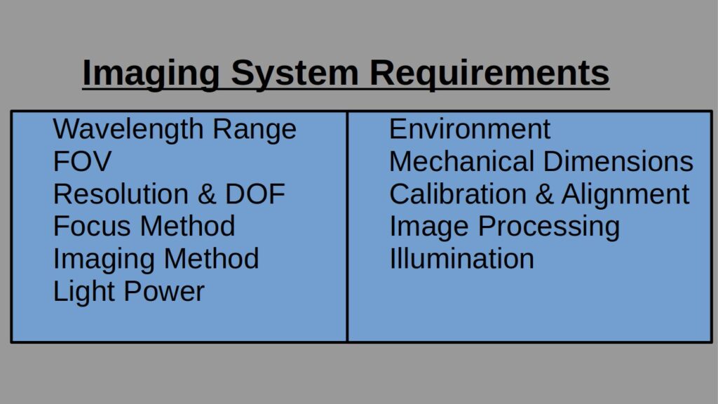
Wavelength Range
VIS, UV, IR? In VIS, do we need the whole 400-700nm spectrum range or will the greens only suffice? Still in VIS, do we need a color camera or a monochrome? Here there are two different points to consider in the wavelength range. The first one is the physics of our problem: if the physical imaging can only be done in IR, we need IR and there is not much we could do about it. However, in the VIS range we have also to consider the Image Processing (see below). If all of our image processing is done on gray images there is not much point in having a color camera, is there?
The impact of the way we define our wavelength range can be dramatic when it comes to camera selection, a topic to which I will dedicate a post. For example, the title “NIR” may require an InGaAs sensor-based camera which is a completely different story from that of a Si sensor-based camera in so many aspects: performance, price, camera features, pixel sizes and many more but had we have written “920-970nm” we would have found out that quite a few Si sensors with enhanced NIR feature support these wavelengths.
Wavelength Range 400-700 (VIS)
Color camera needed: No
Field Of View (FOV)
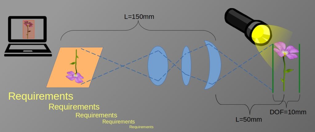
What is the size of object we have to image? Does that include spares? Besides the obvious reason that we do not want our object’s image to be cut somewhere in the middle, in optical systems that include telecentric optics for example the FOV size determines directly the outer lens diameter – not an insignificant thing. Remember that the outcome of the FOV requirements may result in a scanning system in the XY axes. If there is a systematic limitation that forces you to have the image taken in a single shot make sure to have it written down in your requirements.
FOV 24mmX36mm, no scanning allowed
Resolution and Depth of Field (DOF)
We have covered how to correctly define resolution via MTF in a previous post, but in a nutshell, we have to understand what is the smallest element to dissolve by the optical system, what contrast (MTF) level the algo requires this minimum sized element to be and what is the depth in the focus axis we require this contrast to hold. The size of the element may be defined in [um] or in [lp/mm]. If there are more than one constraint have them listed from the smallest element to the largest, as follows:
Resolution / DOF:32 lp/mm @ MTF=20% / 5mm; 16 lp/mm @ MTF=45% / 10mm
Focus Method
The focus method is a derived requirement from the DOF, however it has a very big impact over the optical system such that very early in the process you must know what your limitations are. In the requirement level there are not many options here: it is either fixed focus or variable focus. Fixed focus is simply an optical system with a single focus point and all the object fits in the DOF, for example an optical system looking at objects traveling on a conveyor. Variable focus may be required for multiple reasons but essentially it is because the DOF is not long enough to cover the object’s required height. The implementation of variable focus can be achieved by many methods; from a simple manual translation stage, through complex moving parts and up to liquid lenses and electro-optic devices.
Focus method: variable focus
Imaging Method
By imaging method, I refer to what way the light goes from the object to the imaging system: bright field (front or back illuminated), laser spot, dark field or side illumination, fluorescence, ionic excitation, light scattering, interferometry, spectrometry or any other kind you may come across. Even if it does not seem to be important, since “an image is an image”, have it in your requirement list.
Imaging method: front illuminated bright field
Power
How much light, be it a camera or the human eye, do we expect to get per unit area in our sensor? This can dramatically change the design. The most important thing to know is whether we have “light starvation” or light flooding. If we do not know how to estimate the amount of light reaching the collection optics, we could assess how much light is directed from the object towards the collection and have the optical design take it from there.
Light power: illumination of 100mW reaching the object with expected average reflectance of 10%, minimum reflectance of 2% and max reflectance of 12%
Environment
It goes almost without saying that an underwater camera will not have the same optical considerations as a land camera. If the imaging is to be done inside a furnace that goes from room temperature and up to 250C, this is something we must take into consideration at the very beginning of our design. Vibrations are also a part of it: whether the device is hand-held or installed on top of an army tank turret would make a lot of difference in the final outcome. I had a case where the object was held at a very high temperature which, as a result of air flow in and out of the cavity, completely changed the refractive index of the air in the vicinity of the collection objective which, over time, changed the focus of the system. BTW, the solution for this particular issue was not via the optical design, but we learnt about it only through the optics.
Environment: air, temperature 10-85C, moist > 75%, stationary inside a controller room.
Mechanical Dimensions
There is a difference between how we approach optics that have to fit into a cell-phone and optics that may fit into a 250mmX250mmX250mm cube. To make sure we direct our attention towards the right solution the size limitations, from the very outset of the imaging system concept designs, are very important. If separate physically, have these limitations for both the collection and the illumination.
Mechanical max dimensions collection: 200mmX150mmX150mm
Mechanical dimensions illumination tube: tube radius <= 15mm, tube length <= 200mm
Calibration and Alignment Process and Limitations
In complex optical systems we cannot avoid calibration and alignment processes. It is important to make a note of what our limitations are when it comes to making the optical system operational. First, what human resources are at our disposal and in what environment. With all due respect, we would have a different process complexity level limitation for a diploma technician who is performing an alignment process in the field as opposed to the process limitation for a PhD student who sits inside a quiet optics laboratory. Furthermore, we need to get from our System Engineer what the duty cycle of the system is and how much down time is allowed for auto-calibrations, what the maintenance frequency for the system is and so on. This data gives us a lot of information as to how robust the system is, regardless whether it is an imaging system or any other kind of a system. For example, I am quite positive that the requirements for the James Webb telescope had a one-time alignment, and all the rest was auto-calibrations.
Max downtime for calibration: 1min / 24 hours
Maintenance frequency: 1 day / 12 months – done by a certified technician
Image Processing
We have already covered how the optics and the algo are part of the same system in a previous post. That is where to have it noted. If you have the algo, great. If you have only an idea of the algo, also good. But if you do not have anything yet, have it as TBD and make sure to have the optical designers know what it is once you have it.
Image processing: blob detection using classic image processing such as adaptive thresholding and differential calculations
Illumination
I will dedicate a special post for illumination only, but until then we have to remember that the illumination is an integral part of the optical system. We sometimes neglect this particular part either because we take it for granted or because we believe it is simpler than the collection optics. In most optical systems that is not the case. If our imaging system uses sunlight as its illumination source, we have to take into account a dark cloudy day as well as a summer cloudless bright day. When we plan a 0.75NA microscope we have to make sure that the illumination also sheds light over the target object with at least the same NA. If we also refer to technical aspects of the light source like the wavelength ranges needed for our system, we can clearly see that there are a lot of ins and outs when planning the illumination optics and as such we in many cases have to treat it as a separate optical-sub-module. So illumination requirements have to include their own technical parameters such as Illumination Field, Illumination Power, Light Coherence, Illumination Angles and NA, Illumination spot shape etc.
Just to give a bit of a non-orthodox illumination solution, let’s take for example a case where high power density illumination that covers our required FOV is very expensive and\or complex, so we could use long camera exposure and scan the object’s surface with smaller spot size and integrate it in the final image. But, as stated before, more about illumination in a dedicated post.
There are more parameters to take into account when designing the imaging system, however the main optical trade-offs will be determined by the main points listed in this post.
To sum up, an imaging system is a complex and an interesting one. When we first formulate the requirements for such a system, we have to take care of a lot of parameters to achieve the optimal result so that we could have this system, to our utmost satisfaction, integrated into our final product.